What Are As-Built Construction Drawings?
Construction drawings are an important tool for architects, engineers, and contractors, as they provide accurate and detailed technical information about a building or project site.
There are many terms used to describe construction drawings. They can also be referred to as architectural drawings, as-built drawings, construction plans, 2D drawings, CAD drawings, blueprints, technical drawings, structural drawings, and finishing drawings.
Whatever term you use, before project planning begins, the first step should be to obtain a set of construction drawings, drawn to scale, that document a building’s existing architecture, mechanical systems, and layout.
As-built drawings are created using a CAD software (Computer-Aided-Design) like AutoCAD or a BIM software (Building Information Modeling) such as Revit.
There are many types of CAD drawings that are commonly used. Here, we will explain the common CAD drawings that can be created for your project.
CAD Drawings Explained
Site Plans
A site plan, sometimes referred to as a plot plan, is the graphic representation of all existing site conditions. The site plan maps the entire layout of the project site, including the location of buildings, paving, utilities, and terrain features in a single depiction.
Floor Plans
Floor plans show the layout and spatial relationship between rooms, spaces, and elements such as walls, doors, windows, and furniture. Architects, engineers and builders use floor plans for design and retrofit projects.
Interior Elevations
Interior elevation drawings are 2D drawings that show the interior of a building from various angles. They are used to show the size and shape of a building, as well as the placement of windows, doors, and other features.
Exterior Elevations
Exterior elevation drawings are used to show how a building looks from the outside. It documents the outline of a building, and the placement of windows and doors. Design professionals would request as-built exterior elevations to understand how the different levels of a building stack, and how the windows and doors align and are placed.
Sections or Cross Sections
Sections are 2D drawings that show the cutaway view of a building, structure, or object, disclosing details of the internal structure.
Details
Details are 2D drawings that show a specific element of a building, structure or object enlarged in more detail. The element is scaled for dimensioning and clarification purposes.
Isometric Drawings
An isometric drawing is a representation of a 3D object drawn on a flat plane that mainly contains 2D coordinates – the x and y axes. Although it uses the 2D coordinate system, it gives the illusion that a 3D system is being used. Isometric drawings are made by tilting the viewing angle to 30 degrees for all sides in the 2D plane.
Mechanical and Electrical Drawings
These drawings provide detailed information about the plumbing, HVAC, electrical, and other mechanical systems used in a building.
Reflected Ceiling Plan
A reflected ceiling plan shows the outline of the ceilings, the different ceiling levels, vent locations, and the different types of lighting fixtures.
How Can the Building or Site be Measured?
To get precise measurements of a building or site, the best method is to 3D laser scan it. Laser scanning creates an accurate map of the structural and architectural details in the form of a point cloud. Each point captured is converted to a pixel with an x-, y- and z- coordinate. The point cloud captured by the laser scanner is opened in CAD software such as Revit and AutoCAD to generate CAD plans.
Examples of CAD Drawings
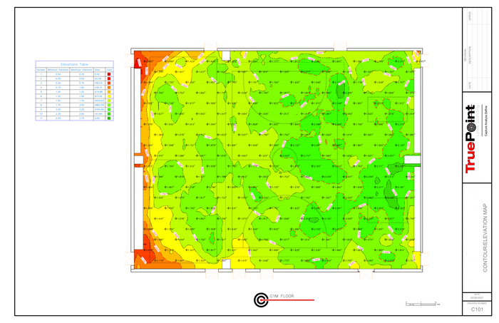
Elevation map and floor contours.
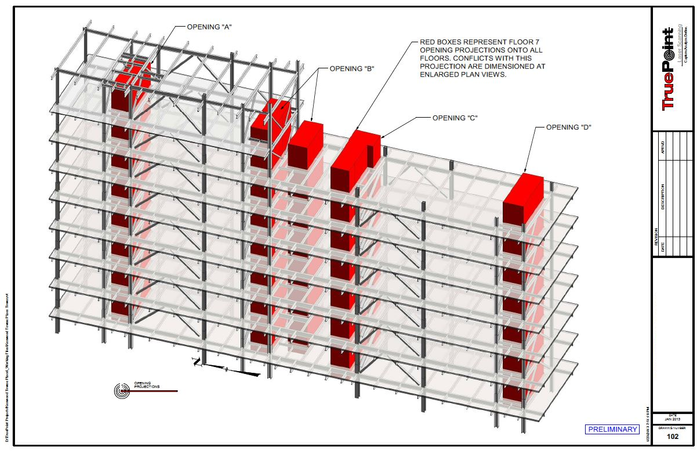
2D plans of elevator shaft alignment.
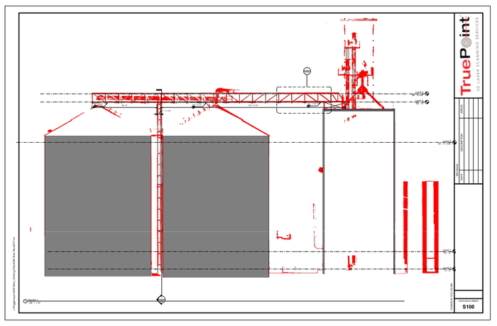
2D drawings of grain silos and overhead bridges and conveyor.
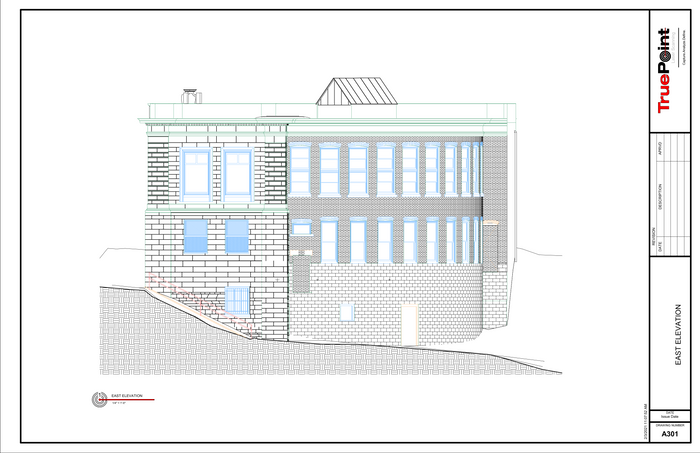
Exterior elevation of historic library.
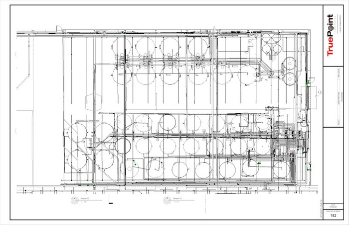
2D floor plan of industrial, automotive, and fleet lubricants manufacturing facility.
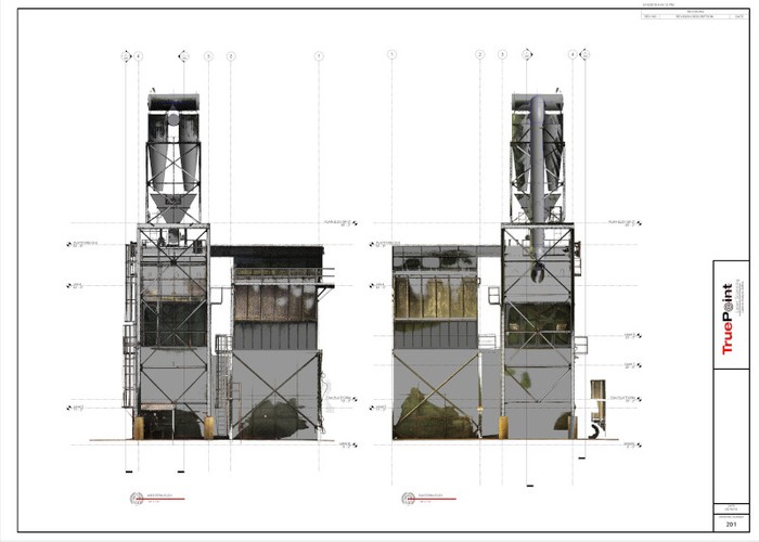
2D CAD elevations of structural tower in paper mill.
For More Information
For more information on construction drawings, as-built drawings, CAD drawings, or 3D laser scanning, contact us today at 419-843-7226 or email info@truepointscanning.com.
Case Studies Equipment Software Deliverables Nationwide Directory Request a Quote