2D CAD Drawings
GPRS 2D CAD Drawing Services
Before project planning begins, many clients desire a set of construction drawings that document the layout of a building’s existing structure, architecture, and mechanical systems. 2D CAD drawings are an important tool, as they provide accurate and detailed technical information about a building or project site.
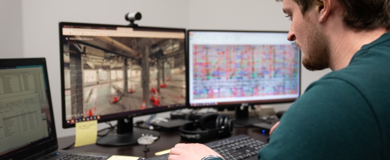
GPRS delivers accurate and customized 2D CAD drawings for your project. First, GPRS 3D laser scans your site using LiDAR technology to capture exact building dimensions, locations, and layout with 2-6mm accuracy. That data is captured in the form of a point cloud. The GPRS Mapping and Modeling Team imports point clouds into CAD or BIM software to create customized 2D CAD drawings with great precision.
Site plans, floor plans, elevations, sections, details, isometric drawings, reflected ceiling plans, and more can be created and are used for construction planning and building modifications. Drawings can be annotated with text, dimensions, leaders, and tables for the client’s needs.
GPRS 2D CAD drawings provide exact dimensions, locations, and layout for a building or project site.
Types of 2D CAD Drawings
Site Plans
A site plan, sometimes referred to as a plot plan, is the graphic representation of all existing site conditions. The site plan maps the entire layout of the project site, including the location of buildings, paving, utilities, and terrain features in a single depiction.
Floor Plans
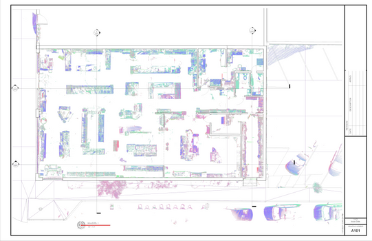
Floor plans show the layout and spatial relationship between rooms, spaces, and elements such as walls, doors, windows, and furniture. Architects, engineers, and builders use floor plans for design and retrofit projects.
Interior Elevations
Interior elevation drawings are 2D drawings that show the interior of a building from various angles. They are used to show the size and shape of a building, as well as the placement of windows, doors, and other features.
Exterior Elevations
Exterior elevation drawings are used to show how a building looks from the outside. They precisely document the outline of a building, and the placement of windows and doors. Design professionals would request as-built exterior elevations to understand how the different levels of a building stack, and how the windows and doors align and are placed.
Sections or Cross Sections
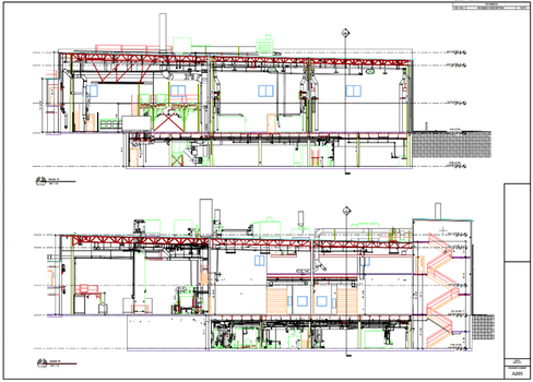
Sections are 2D drawings that show the cutaway view of a building, structure, or object, disclosing details of the internal structure.
Details
Details are 2D drawings that show a specific element of a building, structure, or object enlarged in more detail. The element is scaled for dimensioning and clarification purposes.
Isometric Drawings
An isometric drawing is a representation of a 3D object drawn on a flat plane that mainly contains 2D coordinates – the x and y axes. Although it uses the 2D coordinate system, it gives the illusion that a 3D system is being used. Isometric drawings are made by tilting the viewing angle to 30 degrees for all sides in the 2D plane.
Mechanical and Electrical Drawings
These drawings provide detailed information about the plumbing, HVAC, electrical, and other mechanical systems (MEP) used in a building.
Reflected Ceiling Plan
A reflected ceiling plan shows the outline of the ceilings, the different ceiling levels, vent locations, and the types of lighting fixtures.
Samples of 2D CAD Drawings
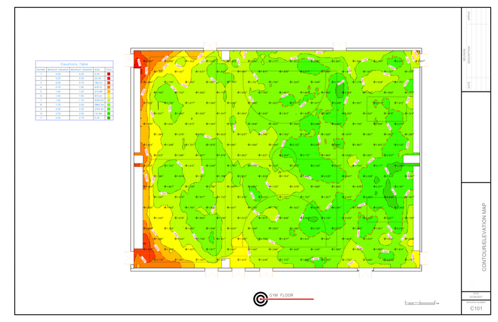
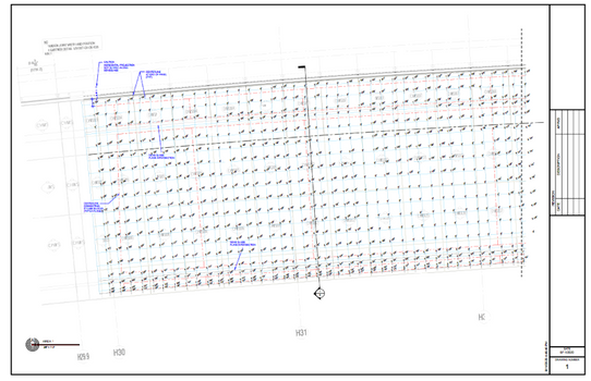
Elevation map and floor contours.
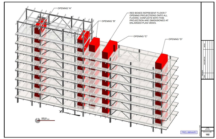
2D plans of elevator shaft alignment.
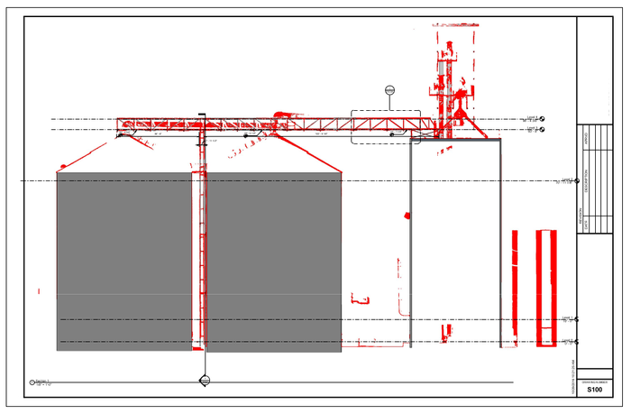
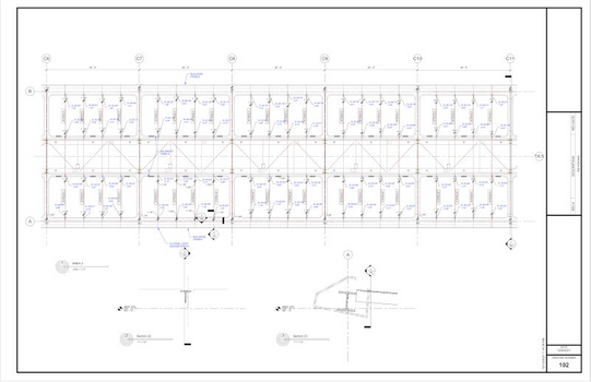
2D drawings of grain silos and overhead bridges and conveyor.

Exterior elevation of historic library.
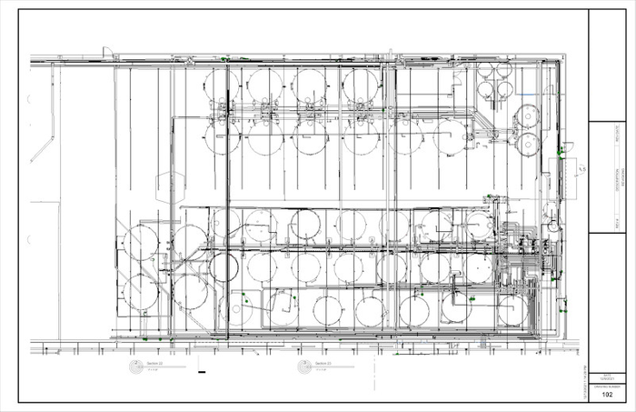
2D floor plan of industrial, automotive, and fleet lubricants manufacturing facility.
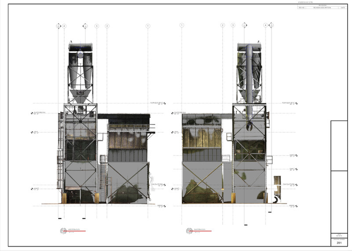
2D CAD elevations of structural tower in paper mill.
Why GPRS? The GPRS Difference.
With GPRS, clients can rest assured that our elite Project Managers use state-of-the-art 3D laser scanning technology to document accurate existing conditions information. Every GPRS Project Manager completes an extensive training program to ensure their competence in laser scanning equipment and field knowledge to provide the best possible results for every project.
We use industry-leading Leica survey-grade laser scanners to capture comprehensive point cloud data. The data produced is complete, clean, accurate, and well filtered with low range noise. Point clouds provide powerful and dynamic information for a project. By representing spatial data as a collection of x, y, and z coordinates, point clouds deliver large datasets that can be mined for information.
Our Mapping & Modeling Team transforms point clouds into 2D CAD drawings, 3D BIM models, 3D meshes, TruViews, and virtual tours of the highest quality standards. Partnering with GPRS means you recieve accurate as built data to expedite project planning and reduce change orders, delays, and costs.
GPRS leads the industry – providing outstanding service and cutting-edge technology – keeping projects on time, reducing risks, and putting relationships with our clients first.
For More Information
For more information on 2D CAD drawings, construction drawings, plan views architectural drawings, as-built drawings, construction plans, 2D drawings, CAD drawings, blueprints, technical drawings, structural drawings, finishing drawings, 2D CAD services, or 3D laser scanning services, contact us today at 419-843-7226 or email laser@gprsinc.com. We’re currently offering 10-minute presentations – would you like to schedule one? Click here.