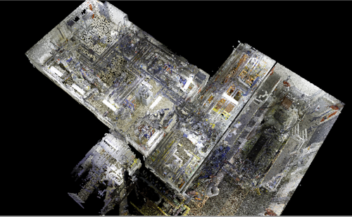
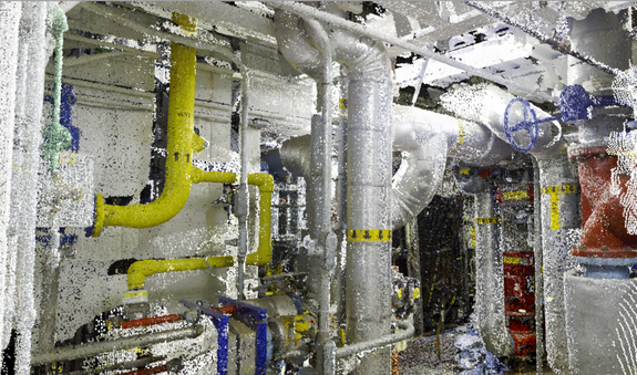
Laser scan data of an engine test cell to plan the relocation of equipment from one test cell to another.
Case Study: 3D Laser Scanning and Modeling Engine Test Cells
"Whether it’s the design and construction of new engine test cells, or the upgrade of existing test cells, a 3D model is a great planning tool for relocation and will help to estimate costs." -- Michelle Colella, Post-Processing Technical Manager
Location: Erie, Pennsylvania
Task: This client was looking to significantly modify the layout of multiple engine test cell rooms, including rearranging existing equipment into different orientations and adding new equipment to the existing structural plan. TruePoint 3D laser scanned 20,000 square feet of as-is conditions of the test cells, plus adjacent equipment and mechanical rooms. TruePoint’s team of in-house engineers created a highly detailed 3D model for use in Autodesk Inventor of all components within the test cells and adjacent rooms.
Challenge: Moving equipment and capabilities from one test cell to another required scoping and advanced planning, as well as engineering and financial forecasting. The engine mounting and engine support systems were being repurposed and had to be moved and the client desired documentation to plan and engineer these components into different test cells. These test cells are in high demand, laser scanning helps minimize downtime by planning and prefabricating in advance, so when the test cell is taken down and set up for a new test, downtime is reduced. It also provides detailed cost estimates on the new components and equipment relocation.
Solutions: Using the Leica ScanStation P50 and the RTC360, TruePoint’s team captured 310 laser scans of the test facility. TruePoint then 3D modeled all engine support structure and systems (including fuel, oil, cooling, air inlet and exhaust and electronic controls) to help this client plan the re-arrangement required to accommodate the new engine type. In order to move capabilities between the different test cells, they also desired structural clearances, mechanical system sizing, layouts and hook-ups. Each system was color coded in the test cell, so they desired that color coding be carried over into the model to help identify systems visually. Using TruePoint’s highly detailed computer model, the client could move pieces of equipment around the space virtually to determine the best real-life scenario for the rearrangement.
Deliverable: The client received a fully registered colorized point cloud of the space, color JetStream Viewer files, and a 3D computer model in Autodesk Inventor of all components within the test cells and adjacent rooms. JetStream Viewer is the free Leica tool to load point cloud data sets to conduct basic navigation and visualization, and calculate measurements.
Added Value: As built documentation and a 3D model for use in AutoCAD and Inventor helped to efficiently complete this project. The client viewed our services and deliverables as an absolute necessity for completing their tasks at this facility. With a highly-detailed, manipulatable 3D depiction of the environment, various team members could access and share the site from the comfort of their computers and collaborate on the redesign of the testing rooms. The team could design and plan in confidence knowing that the dimensional accuracy was far closer and more comprehensive than anything they could have produced from hand measurements alone. The team could also provide an accurate cost estimate of materials and relocation using the 3D model.
TruePoint has extensive experience 3d laser scanning test sites and facilities for the automotive industry. For 3D laser scanning services, call 419-843-7226 or email info@truepointscanning.com.
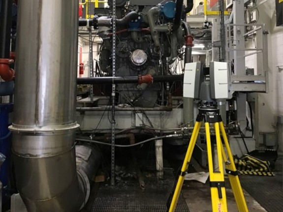
Leica RTC360 quickly and accurately captures colorized point cloud data.
Leica RTC360 laser scanner demonstrating its versatility in a cramped space.
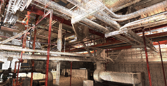
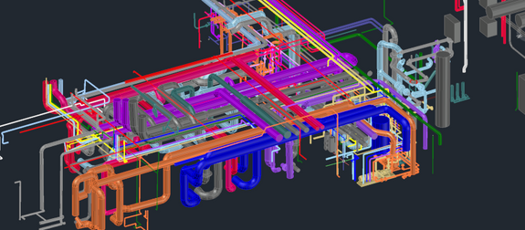
This image shows the support system, piping and ductwork above the test cell. The modeling of this site helped the engineers map the existing area.
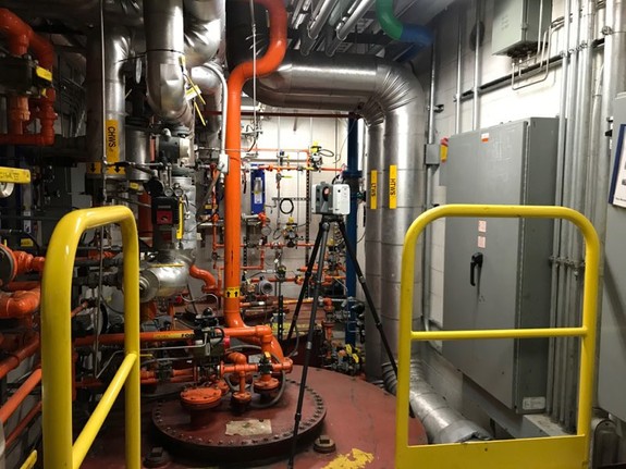
This image shows the dense support system piping in the test cell.
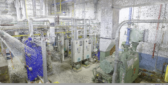
The support systems were documented to help this client plan how to connect and where to place equipment in new test cell.
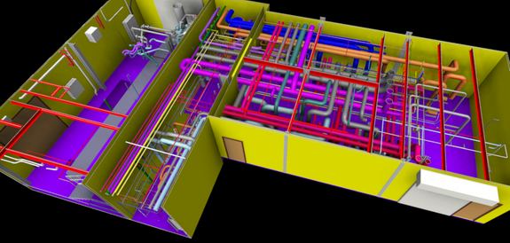
TruePoint’s team of engineers created a highly detailed 3D model for use in Autodesk Inventor of all components within the test cells and adjacent rooms.
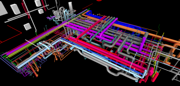
Each system was color coded in the test cell, the client desired that color coding be carried over into the model to help identify systems visually.
With a 3D model, team members could access and share the test cells from the comfort of their computers and collaborate on the redesign.
